Wiggling wires, poking connections, and pressing on contacts…
That kind of thing might be ok on a breadboard or a hand-etched PCB. If you plan on selling your products… well… reliable / solid mechanical connections aren’t optional.
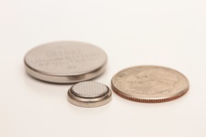
Have you ever used a CR2032 or CR1025 coin-cell battery in a project? They’re great for real-time clocks, can drive simple LED circuits, or can be used as a primary power source for low-power projects.
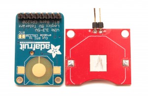
Lookie’ here… two products that use a coin-cell battery!
( Adafruit Ultimate GPS Breakout – left, Sparkfun Coin Cell Battery Breakout – right )
The Sparkfun coin cell battery breakout seemed so darn ‘handy.’ I just had to have one… I mean they’re only a couple bucks!
In the following illustrations, blue represents the PCB, green is soldermask, orange is the copper, and the gray object is a button-cell battery.
You might be able to create an operational contact if you place the soldermask directly on the PCB… maybe. If the board is electronically leveled – it’s a crap-shoot.
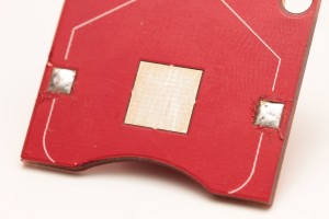
Sadly… in this case, the soldermask on the Sparkfun breakout was placed on top of the copper. If you rub your finger over the soldermask to the pad and back – you’ll feel a slight drop to the pad. Ouch.
So… before you solder on the metal clip, you’ll have to add a glob of solder to fill that monstrous gap between the battery and pad.
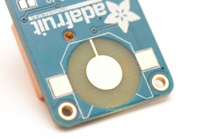
Now… run your fingertip over the soldermask, bare PCB, and battery contact on this awesomtastic Adafruit GPS breakout. This is what you get when you have a ninja assassin design a PCB; a rock-solid battery connector.
In my best David L. Jones accent… “Ooooo, that’s Nice!” Let’s zoom in a bit… and you’ll see exactly what I’m talking about.
Has the thought ever crossed your mind that the bare PCB can be used to your advantage in optimizing a battery connector?

One Response to PCB Design: Keeping Batteries Connected
Trackbacks/Pingbacks